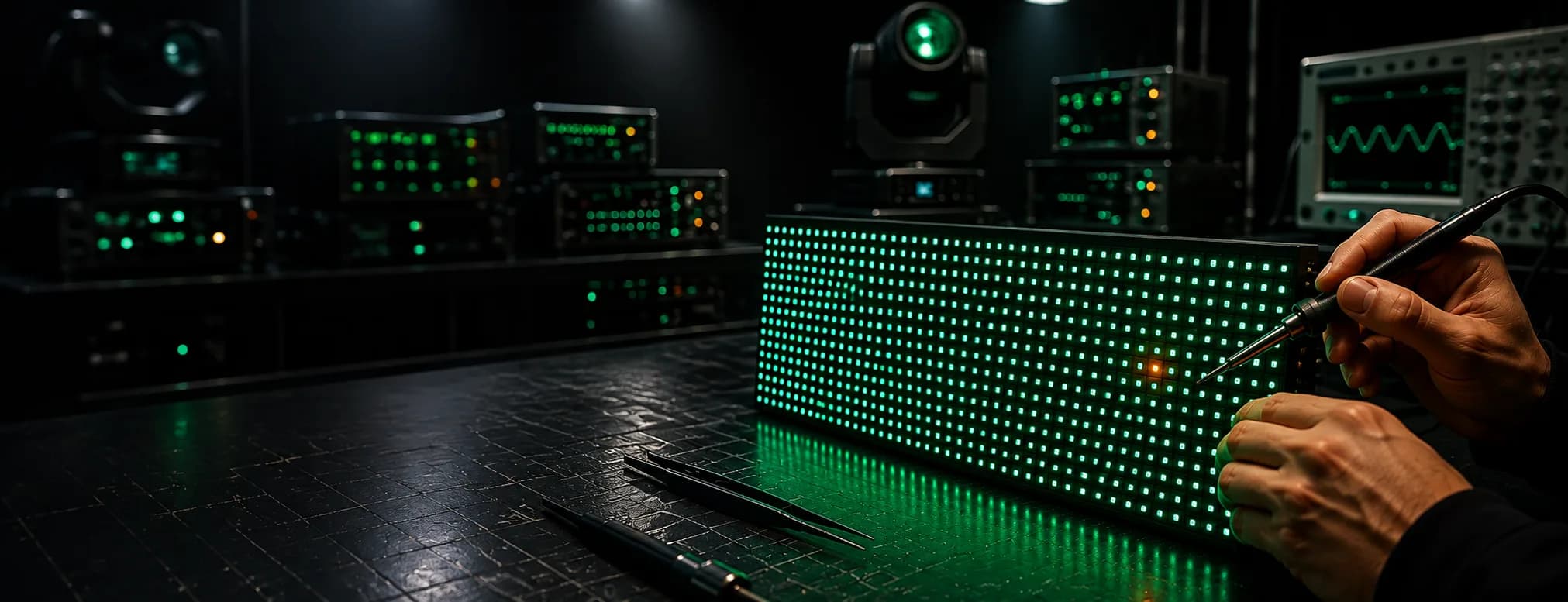
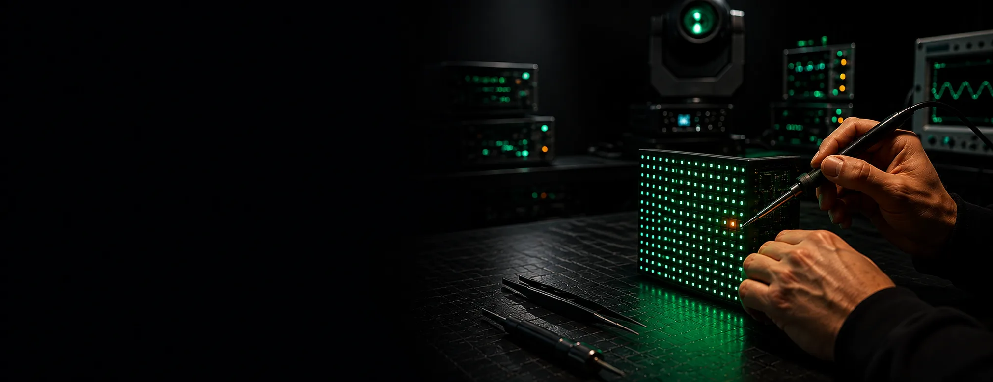
One module on my LED wall is completely black but the panels around it are working fine
One LED module dark, rest of the panel fine: what's failed
A single tile blacked out while its neighbours play video. The fault is local to that module. How to prove it on the wall, and what we can repair at component level.
- Usually
- Module power tail, hub cable or the 74HC245 buffer
- Check first
- 5V (or 3.8V) at the module input header
- Not the card
- A card fault blacks out a whole region, not one tile
- Fixable
- Component level, unless the PCB is cracked through
Nine times out of ten it's the feed into the tile, not the diodes on it. If you've got one LED module dark while the tiles either side of it play video happily, the fault sits in that module's own supply, its hub cable, or the first logic chip behind the input header. Your receiving card is almost certainly innocent. You can prove that in about ten minutes with a meter and a known good spare.
Work it from the wall backwards, in the order we'd work it on the bench.
Rule the receiving card out first
One card drives a lot of pixels. NovaStar's MRV416-N, to take a common example, feeds up to 512 by 512 across sixteen hub outputs, with RGB data split into thirty two parallel groups. When a card dies, everything downstream goes with it. That's several tiles, or the whole cabinet. Not one.
So ask the simple question: are the lit tiles sharing a card with the dark one? If they are, the card is passing data and power exactly as it should. Most current cards also report their own rail voltage and temperature back through the control software, and the rails should sit somewhere in the 3.3 to 5 volt band. Pull that telemetry up before anyone starts undoing thumbscrews (it's free, and it saves you climbing).
Then move the hub cable. Unplug the ribbon feeding the dark tile and plug it into a tile you know works, or swap the dark tile's cable for a neighbour's. If the fault follows the cable, you've found it. What comes back to us most from touring walls is crushed and half seated hub ends, because those ribbons get pinched every time a cabinet goes into a case badly.
Power at the header, before you touch a single IC
Meter across the module's input pins with the wall running. You're looking for 5V on most tiles, or around 3.8V on the low voltage variants that shave power off the driver stage. Anything sagging well below that under full white is a supply problem, not a logic problem.
Three things account for nearly all of it. The screw terminal at the PSU has backed out, the crimp on the power tail has fractured inside the insulation, or the PSU's own output has drifted or dropped a rail. Wiggle test the tail with the wall lit and watch the tile flicker. That's your answer.
If the header reads correct and the tile is still black, the supply has done its job and the fault is on the board.
The chip chain behind one LED module dark
Here's where most of the bench time goes. A whole tile going out at once, rather than one row or one colour, narrows things down usefully, because a full blackout means something upstream of the pixel drivers has stopped.
Start at the 74HC245 buffers. These sit right behind the input header, taking clock, latch, output enable and the RGB data lines off the hub cable and driving them out to the driver chips further down the board. One input feeds several independent outputs, so a failed 245 kills every driver it feeds. Which is usually all of them.
Check them in this order:
- 1.Supply pins on the 245s. An open circuit in the Vcc track under a buffer is a classic, especially on boards that have taken a knock. Repair it with a jumper wire and the tile lights.
- 2.Output enable. If OE is stuck low or shorted to a rail, the drivers stay blanked and the module reads as dead even though data is arriving perfectly.
- 3.The 245s themselves. They're cheap, they fail short after an ESD hit or a hot swap, and replacing them is quick work with hot air.
- 4.Row switching. On older boards that's a 74HC138 decoder driving 4953 P channel MOSFETs on the anodes. Lose the row supply and the tile goes dark with the data still running.
- 5.The constant current drivers. A single failed driver usually costs you one colour across a block, so a total blackout points at them only when the chain is shared.
Newer tiles complicate step four. Integrated parts like the RT5958, DM7258, ICND2013 and ICND2018 combine row switching and constant current drive in one chip, and they're not swappable between families. We identify the exact marking before we order anything, because a near miss part number will fit the footprint and still not work.
One more thing to look for before you commit to rework: cracks. Hold the board to the light and check the corners and the mounting boss areas. A hairline crack through a data track breaks the chain cleanly and mimics a chip failure. On a tile that's been dropped, or one that's been flexed by a bent cabinet, that's a real possibility. Cracked boards across the data bus are the ones we tend to call as scrap, because a jumpered repair through a fractured multilayer never survives another tour.
If your symptom is a block of pixels rather than the whole tile, our guide on dead clusters within a module covers that pattern instead.
What we repair and what we won't
We rework at component level: buffers, decoders, row MOSFETs, driver ICs, hub connectors and lifted supply tracks. That's the bread and butter of LED screen and module repair here, and it keeps discontinued pitches alive when a matched replacement tile no longer exists.
We won't return a board with water corrosion spread through the vias, a mask lifted across the driver footprints, or a crack running through the data bus. Those get flagged and quoted as a module replacement instead, with the calibration matched to the rest of the cabinet. Honest answer: on a heavily corroded tile, a repair costs more than it's worth and fails again in a month.
Every repaired tile runs on test at full white for hours before it ships, because thermal faults love to hide at room temperature.
Safety when the wall is in the air
If the tile is at height, that changes the job. ANSI E1.50-1, revised in 2025, sets out requirements for temporary large format modular LED display structures, covering assembly, suspension, dismantling and the access arrangements needed to get to components safely. It's worth reading before anyone goes up a ladder to swap a module on a hung wall. The published standards are listed by ESTA's Technical Standards Program.
Our usual advice is simple. Ground the cabinet if you can, work on it at bench height, and don't do driver level diagnosis at the top of a scissor lift with a show call in ninety minutes.
Getting one LED module dark repaired
For a single tile, pull it and post it. Our send in repair route suits loose modules and receiving cards, and we'd rather have the hub cable and, if you can spare it, one working tile from the same cabinet for comparison. It speeds up the driver identification considerably.
For a fixed install in a church or a venue, or a wall that can't come down, on site service makes more sense. We bring the hot air, the spares and the meters to you.
Rental houses tend to send us tiles in batches between hires, which is the sensible way to do it: one dark module today is usually three by the end of the season, because the tiles all went out in the same trucks. Tell us what you've got and what the wall does, and we'll tell you what's worth fixing. Start at contact.